Lab 3 Time of Flight Sensors
The purpose of this lab was to gain familiarity with time of flight sensors, one of the first sensors that we will equip our robot with.
I2C Setup
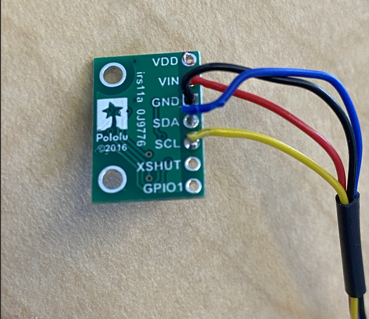
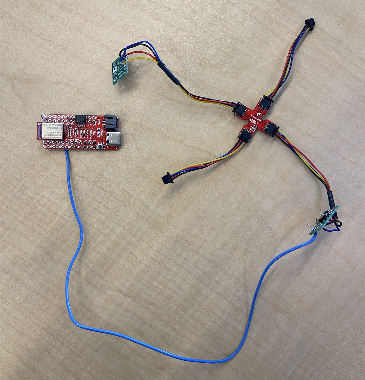
Since we will be using 2 TOF sensors, we have to make sure that we are able to properly process and distinguish the data received from each TOF. The address of one of the sensors is already hardwired on the Artemis, so we must come up with a way to distinguish the two sensors being used. We can either change the address on the software interface or make use of the XSHUT pin on the sensor. The XSHUT pin will hold all sensors connected except for the one that you can then reconfigure. The default I2C address is 0x29, as seen in the image below. I chose to enable the sensors separately through their shutdown pins because you would not need to change the address of the sensors every time they power off. In addition, it is more power and energy efficient but also comes at the cost of communication delays. I didn't use the other method because I did not want to have to change the I2C address every time the sensor is powered off, even though it would give the benefit of less communication delays. I decided to solder the XSHUT pin of one sensor to pin 8 of my Artemis board, which I then used to shut off the corresponding sensor during setup and change the address of the other sensor. In the image below, the address printed is 0x29.

This is how I changed the address of one of the sensors by setting it to 32.
I chose to place both sensors at the front of my robot. I want to measure both distances to be able to develop an accurate frame of reference from the front. As they will be placed next to each other, the robot will kind of have "eyes" or a full point of view and also can account for blind spots in the front. The robot could possibly miss situations on the far sides on both sides if it does not fall in the field of view.
TOF Connections


TOF Modes + Readings
The TOF sensor has 3 modes that can be used - short, medium, and long. Long distance mode allows for the longest range - 4m but is very sensitive to ambient light. Short distance mode is not as sensitive to ambient light, but has a max ranging distance of 1.3m. I chose to use short distance mode because of its resistance against ambient light as it will lessen the overall error as it can operate in a bright area but at the cost of the range distance.
After deciding which mode to use, I used the ReadDistance example from the Soarkfun library on one of the TOF sensors to understand how the short mode would use. I took the measurements in 4 cm increments from 0 cm to 150 cm. I measured this using the white box as a frame of reference as seen in the picture below, and measured The standard deviation of the data is miniscule, confirming the repeatability of the short distance mode. Using the stopRanging() function, I was able to see that the ranging time is 97ms with .stopRanging() and 95ms without the .stopRanging() function.

2 TOF Sensors
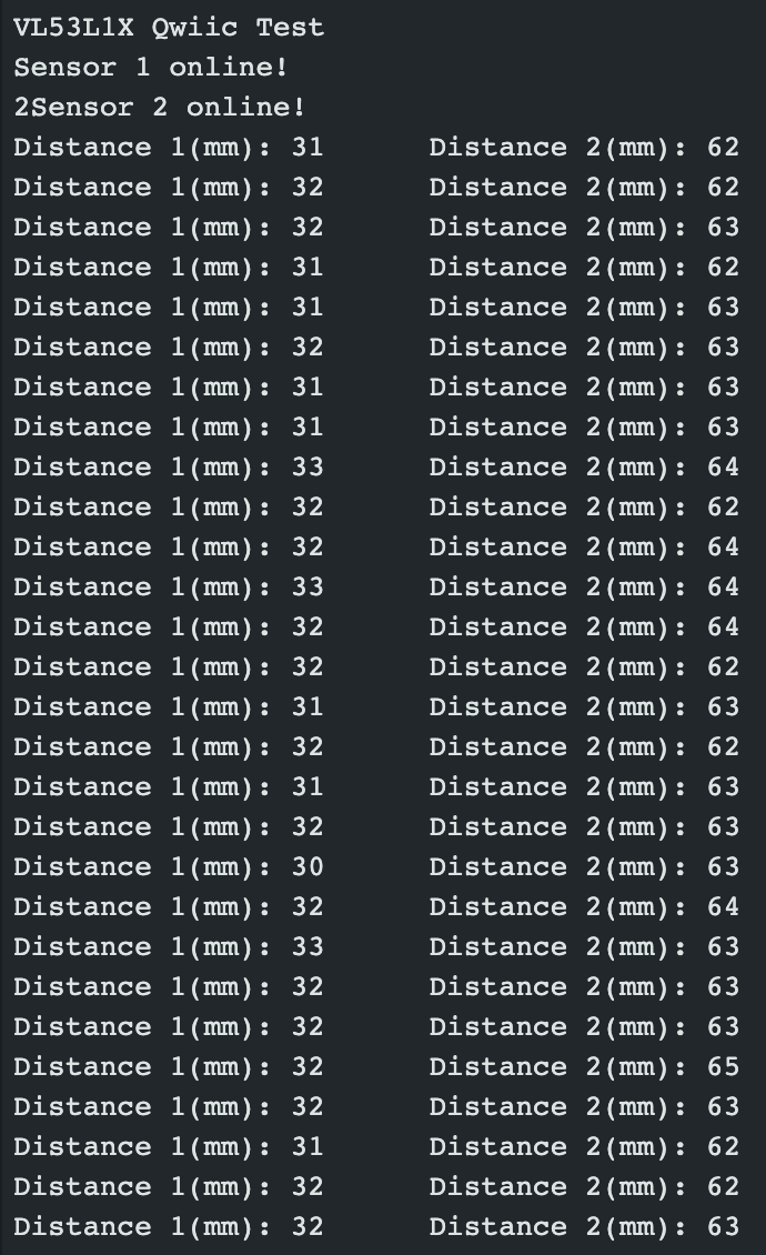
When hooking up both TOF sensors, I had to I set up the initialization of both TOF sensors first, shut down one of the sensors, and change the address of the other sensor. Then the first sensor is turned bck on. My loop takes around 9 ms to execute , and the current limiting factor is how long it takes to check if the new data is ready. One issue that I had faced was the speed of the readings, it would sometimes get stuck and not continue to display the measurements. I used .startRanging() instead of .stopRanging() to only iitialize the sensors once and also used .checkForDataReady() to only print the appropiate distance reading if there is a new reading available. This is similar to the implementation of the notification handler in the previous lab.

TOF + Bluetooth
Combining the TOF sensor data with the bluetooth functionality from the previous lab, I slightly altered the temperature command to instead be able to send TOF sensor data from the Artemis to the computer. To add a new command, the arduino sketch, the cmd_types file, as well as the demo.ipynb file needed to be updated. The new command is able to collect data from both sensors for a specified amount of time and then the computer receives the reading from both sensors.